4 Bit Serial Adder Circuit Diagram
11+ 4 bit adder circuit diagram Adder circuit diagram schematic bit works figure Serial adder
Full-Adder Circuit, The Schematic Diagram and How It Works – Deeptronic
Serial adder bit diagram two Binary adder and parallel adder Adder verilog
Design a serial adder circuit using verilog
Adder alu nor nandAdder serial flip flop parallel binary flipflop use clock electronics stack taken Full-adder circuit, the schematic diagram and how it works – deeptronic.
.


Design a serial adder circuit using Verilog
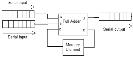
SERIAL ADDER - ELECTRICAL ENCYCLOPEDIA

Binary Adder and Parallel Adder - Electrical Engineering Stack Exchange

Full-Adder Circuit, The Schematic Diagram and How It Works – Deeptronic
